Location:
Low-Voltage Switchgear Series
- Photovoltaic Grid-Connected Series
- Low-Voltage Switchgear Series
- High-Voltage Switchgear Series
- Ring Main Unit, Gas-Fired Switchgear, Solid-State Switchgear Series
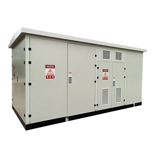
- Prefabricated Substation Series
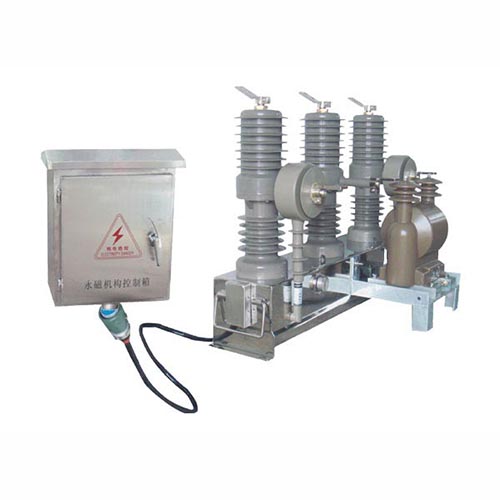
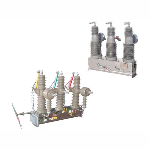
- Outdoor Vacuum Circuit Breaker Series
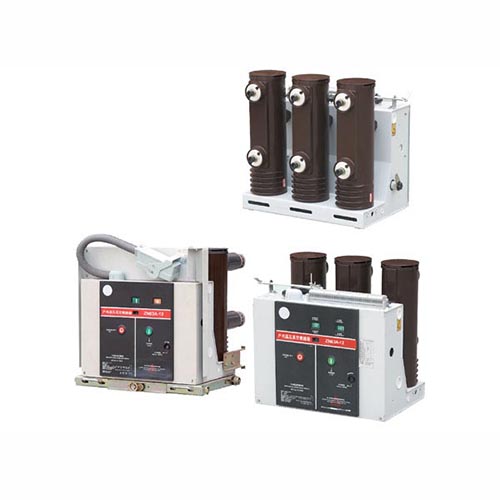
- Indoor Vacuum Circuit Breaker Series
- Power Transformer Series
- Distribution Box Series
- Cable Branch Box
Low-Voltage Switchgear Series
Product Center
- Photovoltaic Grid-Connected Series
- Low-Voltage Switchgear Series
- High-Voltage Switchgear Series
- Ring Main Unit, Gas-Fired Switchgear, Solid-State Switchgear Series
- Prefabricated Substation Series
- Outdoor Vacuum Circuit Breaker Series
- Indoor Vacuum Circuit Breaker Series
- Power Transformer Series
- Distribution Box Series
- Cable Branch Box
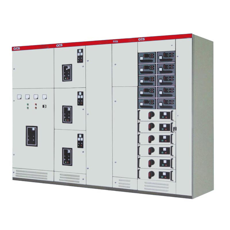
GCS low voltage withdrawable switch cabinet
This product is suitable for three-phase four-wire and three-phase five-wire power discharge and charging with three-phase AC 50/60Hz, rated voltage 380 (400) V~600V; rated current 4000A and below;
- Product Details
- Return
Product introduction
The GCS type low-voltage withdrawable switchgear (hereinafter referred to as the device) is a low-voltage withdrawable switchgear designed and developed by two joint design teams based on the requirements of industry authorities, power users and design units. In order to meet the needs of the growing power market for capacity expansion, computer interfaces, centralized power control, convenient installation and maintenance, and shortened accident handling time, based on the principles of safety, economy, reasonableness, and reliability, it is a low-voltage drawout switchgear that is in line with national conditions, has high technical performance indicators, can adapt to the development needs of the power market, and can compete with currently introduced products.
Structural features
It can increase the heat capacity of the adapter and significantly reduce the additional temperature rise caused by the temperature rise of the adapter to the connector, cable head and partition board.
The separation between functional units and compartments is clear and reliable, and the failure of one unit will not affect the work of other units, so that the failure is limited to a small range.
The flat arrangement of the bus bars makes the device have good dynamic and thermal stability and can withstand the impact of 80/176kA short-circuit current.
The number of circuits in a single MCC cabinet is up to 44 circuits, which fully considers the needs of automated electric doors/unit groups in large-capacity power plants, petrochemical systems and other industries.
Connections to external cables are made in the cable compartment, which can be accessed up and down.
In the same power distribution system, the short-circuit current can be limited by current-limiting reactor matching, the bus voltage can be stabilized at a certain value, and the requirements for the short-circuit strength of components can also be partially reduced.
The drawer unit has a sufficient number of secondary connectors (32 pairs for unit 1 and above, 20 pairs for unit 1/2), which can meet the requirements for computer interfaces and automatic control loop docking points.
Technical parameters
| project | unit | data | |
| Main circuit rated voltage | V | AC 380(400)、(660) | |
| Auxiliary circuit rated voltage | V | AC 220、380(400) DC 110、220 | |
| Rated frequency | Hz | 50(60) | |
| Rated insulation voltage | V | 600(1000) | |
| Rated current | Horizontal bus | A | ≤5000 |
| Rated current | Vertical Busbar (MCC) | A | 1000 |
| Busbar rated short-time withstand current (1s) | kA | 50、80 | |
| Busbar rated peak withstand current (0.1s) | kA | 105、176 | |
| Power frequency test voltage (1min) | Main circuit | V | 2500 |
| Power frequency test voltage (1min) | Auxiliary circuit | V | 1760 |
| busbar | Three-phase four-wire system | A、B、C、PEN | |
| busbar | Three-phase five-wire system | A、B、C、PE、N | |
| Protection level | IP30、IP40 | ||
Appearance and installation dimensions
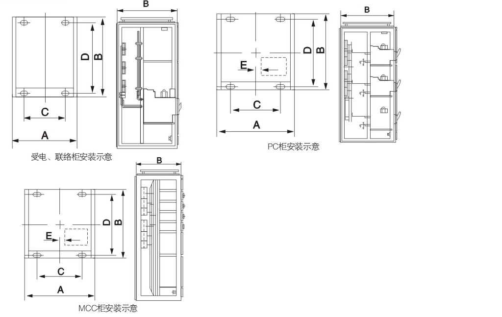
| General cabinet code | A | B | C | D | E | F×G |
| GCS-TG1010-2 | 1000 | 1000 | 850 | 956 | 60 | 400×400 |
| GCS-TG0810-2 | 800 | 1000 | 650 | 956 | 160 | 400×400 |
| GCS-TG1008-2 | 1000 | 800 | 850 | 756 | 60 | 400×400 |
| GCS-TG0808-2 | 800 | 800 | 650 | 756 | 160 | 400×400 |